Special Duty Class 08

The SD-08 is a civilian star-hopper designed for in-system and short-range inter-system travel.
Procedures
Hypermagnetopulse
Setup
-
Ensure all are true:
- Both BUS breakers are IN;
- Both BATT breakers are IN;
- Both BATT VOLT meters read at least 40V;
- Both BATT CHRG breakers are set to DSCH;
- The CENTRAL MODULE TCS HOT LOOP PUMP and CONTROL UNIT is active;
- ALL breakers under HYPERMAGNETOPULSE SYSTEMS and HMP HARDPOINT MANAGEMENT are in the OUT position.
- On breaker board, HYPERMAGNETOPULSE SYSTEMS:
- Set MAIN POWER to IN.
- Set CONTROL UNIT to IN.
- If reactor is active, set REACTOR COUPLING to IN.
- On breaker board, HMP HARDPOINT MANAGEMENT:
- Set all MAG HDPTS to IN.
- Set COLD LOOP PUMP to MAIN.
- Wait for COLD LOOP TEMP to fall into the green area, or under 30 K.
- On breaker board, HYPERMAGNETOPULSE SYSTEMS:
- Observe HARDPOINT STATUS display.
- If all are GREEN, proceed.
- If one or more are YELLOW:
- Wait for temperatures to equalise between hardpoints.
- If there is a persistent anomaly between the COLD LOOP TEMP and any MAG HDPT TEMP, see TROUBLESHOOTING: HYPERMAGNETOPULSE HARDPOINT FAILURE.
- If one or more are RED, see TROUBLESHOOTING: HYPERMAGNETOPULSE HARDPOINT FAILURE.
- Set CAP STATE to CHRG.
- Observe HARDPOINT STATUS display.
Reactor
Start
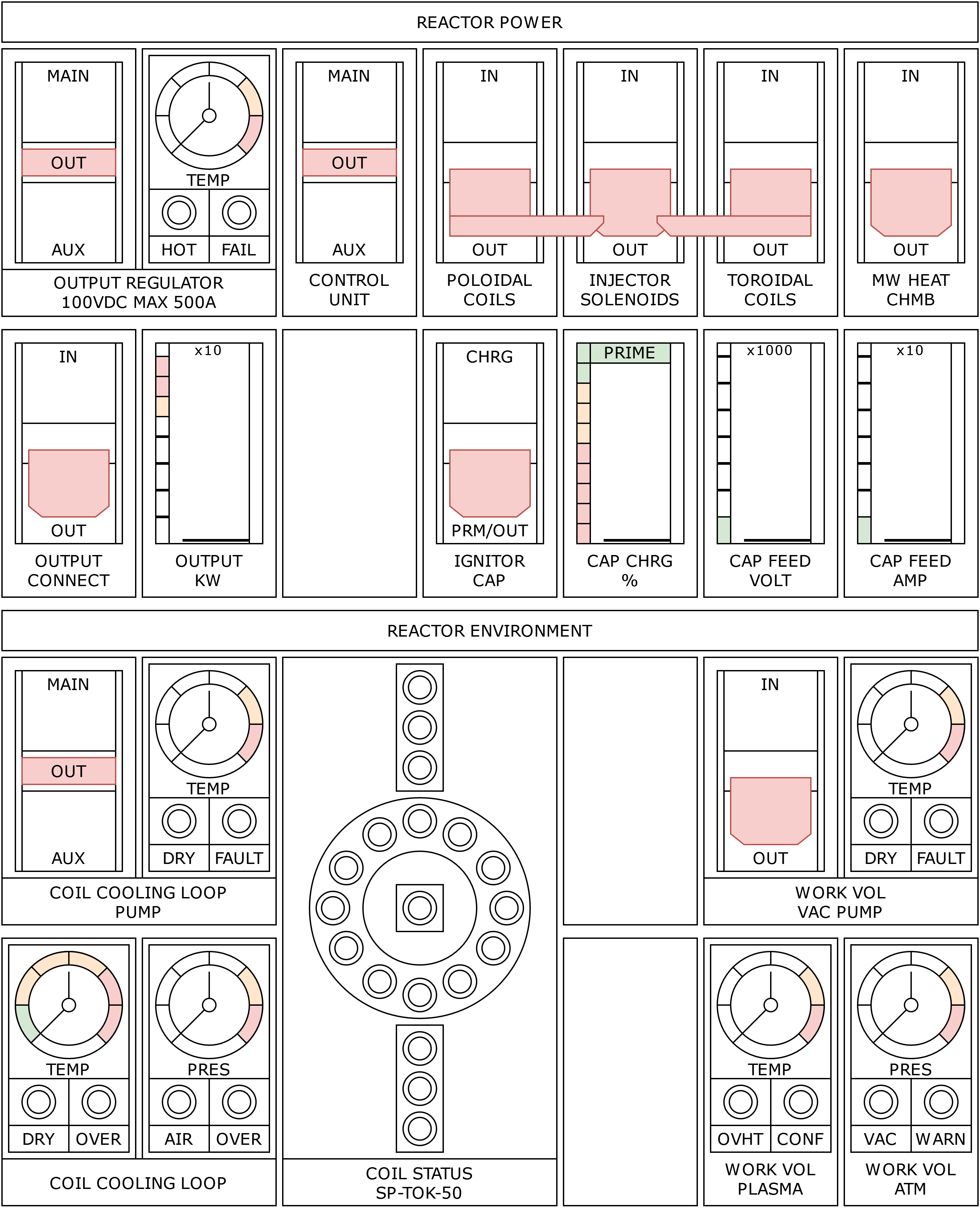
-
Ensure all are true:
- Both BUS breakers are IN;
- Both BATT breakers are IN;
- Both BATT VOLT meters read at least 40V;
- Both BATT CHRG breakers are set to DSCH;
- The CENTRAL MODULE TCS HOT LOOP PUMP and CONTROL UNIT is active;
- ALL breakers under REACTOR SYSTEMS are in the OUT position.
-
On breaker board, REACTOR POWER and ENVIRONMENT:
- Set CONTROL UNIT to MAIN.
- Set COIL COOLING LOOP PUMP to MAIN.
- Wait for COIL COOLING LOOP TEMP to fall into the green area, or under 30 K.
- Set POLOIDAL and TOROIDAL COILS to IN.
-
On control desk, left section, REACTOR CONTROL:
-
Depress REACTOR SELF-TEST button for five (5) seconds.
- If button rimlight illuminates, proceed.
- If cockpit master alarm sounds, see TROUBLESHOOTING: REACTOR SELF-TEST.
-
Depress REACTOR SELF-TEST button for five (5) seconds.
-
On breaker board, REACTOR POWER and ENVIRONMENT:
- Ensure COIL COOLING LOOP TEMP is still inside green zone.
- Set WORK VOL VAC PUMP to IN.
- Set MW HEAT CHMB to IN.
- Set IGNITOR CAP to CHRG.
- Set INJECTOR SOLENOIDS to IN.
-
On control desk, left section, REACTOR CONTROL:
- Set WORK VOL VAC PUMP knob to VAC.
- Wait for WORK VOL PRES to fall into the green area, or under 1×10⁻⁴ atm.
- Set WORK VOL VAC PUMP knob to WORK.
-
Lift INJECT/SUSTAIN cover and depress button for two (2) seconds.
- If button rimlight illuminates, proceed.
- If cockpit master alarm sounds, see TROUBLESHOOTING: REACTOR INJECT/SUSTAIN.
-
Lift PERISTALSIS cover and depress button.
- If button does not illuminate or remain depressed, see TROUBLESHOOTING: REACTOR PERISTALSIS.
-
Observe WORK VOL PLASMA TEMP.
- Once above 1×10⁷ K, proceed.
- If the temperature does not reach this threshold within 10 minutes, see TROUBLESHOOTING: REACTOR PLASMA TEMPERATURE.
-
On breaker board, REACTOR POWER:
-
Check IGNITOR CAP CHRG.
- If reading is in PRIME region, proceed.
- If capacitor does not show a level despite IGNITOR CAP breaker in CHRG position, see TROUBLESHOOTING: REACTOR IGNITOR CAPACITOR.
- Set IGNITOR CAP to PRM/OUT.
-
Check IGNITOR CAP CHRG.
-
On control desk, left section, REACTOR CONTROL:
- Lift IGNITE cover and depress button.
-
Observe WORK VOL PLASMA TEMP.
- Reading should spike to at least 1×10⁸ K.
- If no spike is registered, set breaker board IGNITOR CAP to CHRG and return to step 6.
- If problem persists, see TROUBLESHOOTING: REACTOR IGNITION FAILURE.
-
On breaker board, REACTOR POWER:
- Set OUTPUT REGULATOR to MAIN.
- Set OUTPUT CONNECT to IN.
-
On breaker board, BUS & BATTERIES:
- Set BUS B to OUT.
- Set both BATT CHRG breakers to AUTO.
Configuration
Troubleshooting
Electronics
Control Failure
Reactor
Self-Test
This procedure assumes that PROCEDURES: REACTOR START setup has been performed, the REACTOR SELF-TEST button has been depressed for five (5) seconds and the cockpit master alarm has been activated.
- Acknowledge master alarm.
- If master alarm is silenced, proceed.
- If master alarm continues to sound, see TROUBLESHOOTING: ELECTRONICS CONTROL FAILURE.
- Depress REACTOR SELF-TEST button for five (5) seconds.
- If master alarm is activated, acknowledge and proceed.
- If self-test succeeds, return to PROCEDURES: REACTOR START and continue from step 4.
- On breaker board, REACTOR POWER, set CONTROL UNIT to AUX.
- On control desk, left section, REACTOR CONTROL, repeat step 2.
- If master alarm is activated, silence and proceed to step 5.
- On breaker board, REACTOR POWER, check state of COILS breakers.
- If both are IN, proceed.
- If one or both are OUT, see EMERGENCIES: REACTOR GENERAL FAILURE.
- In storage volume, on REACTOR COMPUTER, check display for alerts:
- "SELF TEST FAIL" should be visible.
- If it isn't, check breaker board, REACTOR POWER, CONTROL UNIT is not OFF.
- If both MAIN and AUX CONTROL UNIT settings do not show alerts after REACTOR SELF TEST has been depressed, see EMERGENCIES: REACTOR GENERAL FAILURE.
- If "CONFIG!" is printed, reactor configuration is invalid. See PROCEDURES: REACTOR CONFIGURATION.
- If "HOT!" is printed, reactor coils are too warm to operate. Return to PROCEDURES: REACTOR STARTUP step 2.
- If "PRES!" is printed, reactor contains significant gas pressure.
- Perform PROCEDURES: REACTOR STARTUP step 5.1 to 5.3.
- Perform TROUBLESHOOTING: REACTOR SELF-TEST step 2.
- If both fail, proceed.
- If no alert is printed, proceed.
- "SELF TEST FAIL" should be visible.
- On REACTOR COMPUTER:
- Initiate factory reset.
- Perform PROCEDURES: REACTOR CONFIGURATION.
- Perform TROUBLESHOOTING: REACTOR SELF-TEST step 2.
- If issues persists, proceed.
- The reactor has likely experienced a failure. See EMERGENCIES: REACTOR GENERAL FAILURE.
Emergencies
Reactor
General Failure
Hot Coils
An active reactor with hot coils is an emergency. Further operation could result in damage to the hardware and collapse of the magnetic containment field.

